LR & RC Phase Relations
From UO Physics Demonstration Catalog
Return to Circuits
Description:
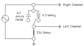
An inductor or a capacitor is in series with a resistor. The connections shown are made to an oscilloscope. The Right channel monitors the input voltage and the Left channel monitors the current by measuring the voltage across the resistor. .By switching between the inductor and the capacitor, the change in phase relationships of voltage and current can be observed.
Location:
UPDATE LOCATION OF MATERIALS
