Difference between revisions of "LRC Series Resonance"
From UO Physics Demonstration Catalog
(Added picture.) |
|||
| Line 4: | Line 4: | ||
'''Seeing the Resonant frequency:''' Set the Frequency generator to a low frequency Square Wave and you will see a decaying sine wave whenevr the square wave shnages polarity. This shows the ringing Resonant Frequency of the LRC circuit | '''Seeing the Resonant frequency:''' Set the Frequency generator to a low frequency Square Wave and you will see a decaying sine wave whenevr the square wave shnages polarity. This shows the ringing Resonant Frequency of the LRC circuit | ||
[[File:New demo.jpg|thumb]] | |||
'''Location:''' | '''Location:''' | ||
* | * | ||
Latest revision as of 10:29, 9 June 2023
Return to Circuits
Description:
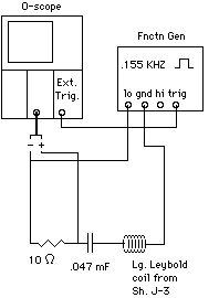
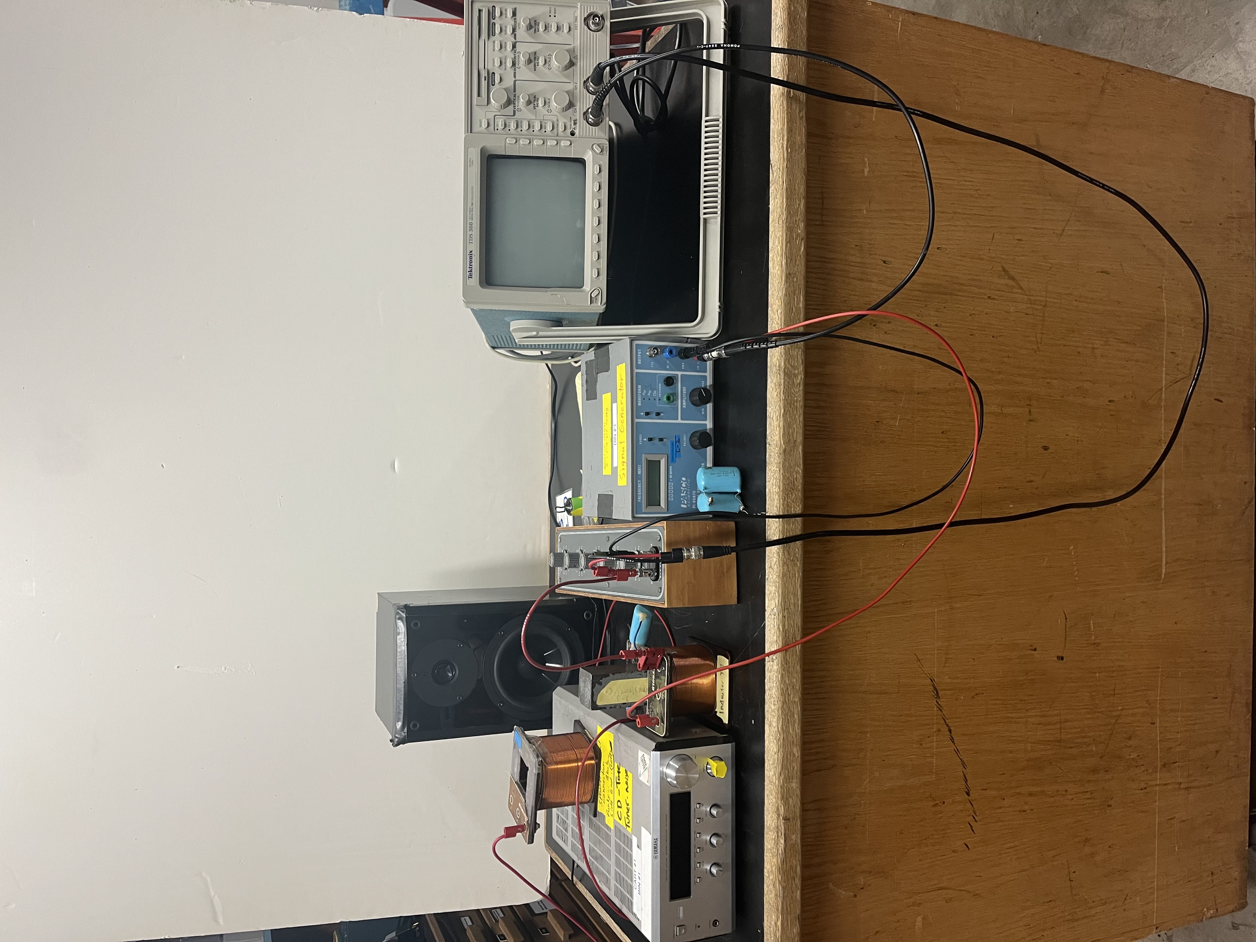
An inductor, resistor, and capacitor are connected in series. Monitor the current in the circuit by measuring the voltage across the resistor. The frequency from the function generator is varied and resonance is found when the current (voltage across the resistor) is a maximum. You can change the resonant frequency by changing the inductance by putting and iron core inside the coil and again find the resonance. You can aslo set the frequency generator close to resonance and show how you can tune the circuit into resonance by moving the iron core in and out of the coil until you find the position of the iron core that makes the current a maximum.
Seeing the Resonant frequency: Set the Frequency generator to a low frequency Square Wave and you will see a decaying sine wave whenevr the square wave shnages polarity. This shows the ringing Resonant Frequency of the LRC circuit
Location:

